1. Function of crankshaft position sensor
The crankshaft position sensor is a sensor shared by the ignition system and the fuel injection system. It is used to detect the crankshaft angle of the engine and the top dead center of the piston, and send the detection signal to the engine computer in time to measure the engine speed and confirm the position of the piston in the cylinder. Used to control ignition timing and fuel injection timing.
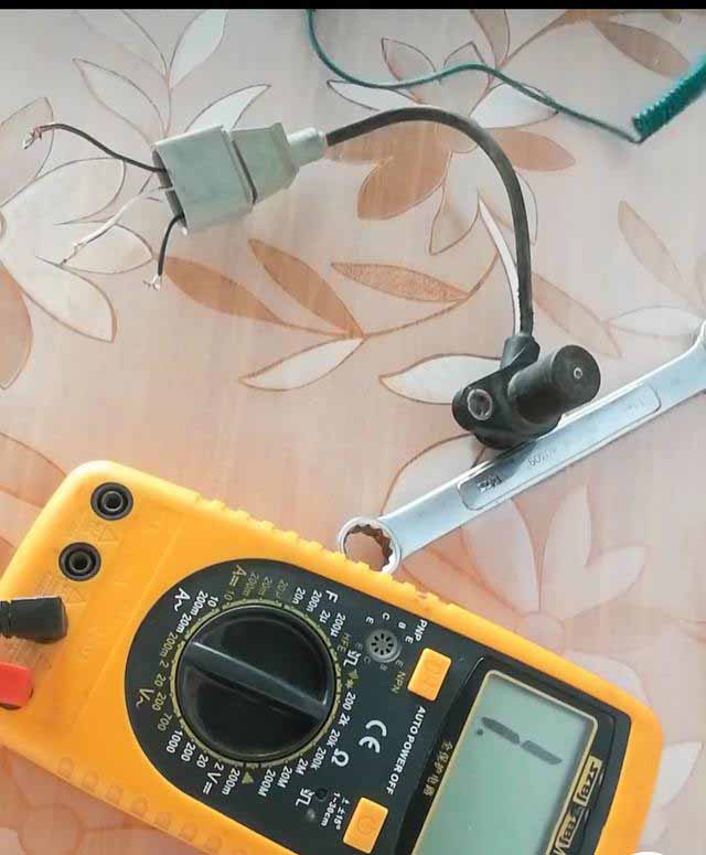
2. Composition of crankshaft position sensor
Three, the working principle of the crankshaft position sensor
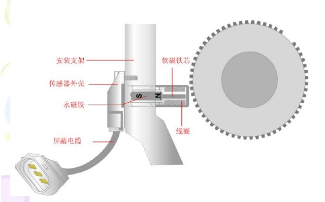
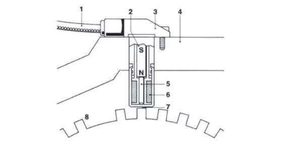
Electromagnetic crankshaft position sensor: When the engine is rotating, the magnetic field passing through the induction coil changes due to the change in the position of the timing tooth of the signal plate relative to the induction coil. When the timing tooth of the cylinder approaches the coil, the air gap becomes smaller and the magnetic resistance of the magnetic circuit When the timing tooth is aligned with the coil, the magnetic flux reaches the maximum value; when the timing tooth leaves the coil, the magnetic flux starts to decrease. In this way, each timing tooth will cause the magnetic flux in the coil to change from zero to the maximum, and from the maximum to zero periodically, thereby generating a sine wave-like induced electromotive force output in the induction coil, whose magnitude is proportional to the magnetic flux. The rate of change is directly proportional. After shaping and amplifying the above output signal, it is input into the engine electronic control unit, and the electronic control unit can determine the engine speed and crankshaft position, and correct the ignition timing and fuel injection according to the signal.
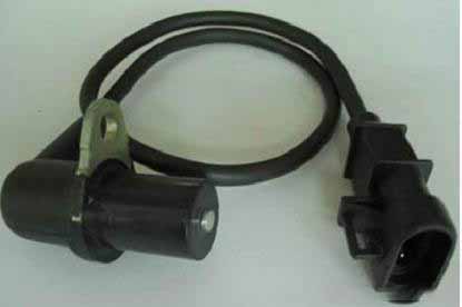
Four, crankshaft position sensor detection
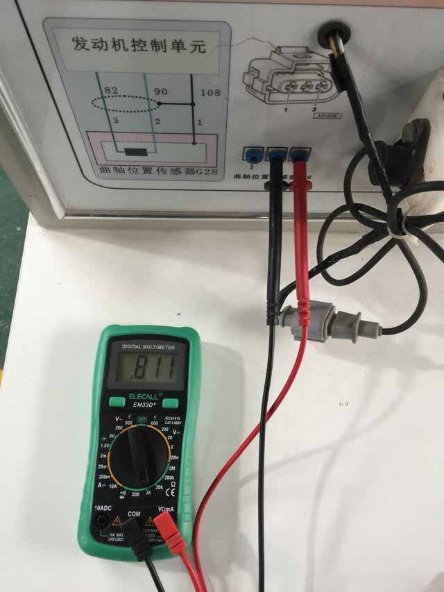
1. Turn off the ignition switch, set the multimeter to the 2KΩ position, and measure the resistance of the crankshaft position sensor. The resistance range is 480-1000Ω. Use a multimeter to measure the resistance value of pins 2 and 3, and the actual measured resistance value is 811Ω, which is within the normal range, indicating that the sensor itself has no fault.
2. Measure the voltage, adjust the multimeter to the AC 200V position, start the crankshaft sensor signal wheel, and measure the voltage between the 2nd and 3rd pins. The voltage should be within 3V. If the measured voltage is greater than 3V, it proves that the clearance between the crankshaft position sensor and the signal wheel (gear) is too small; if the measured voltage is less than 3V, it proves that the clearance between the crankshaft position sensor and the signal wheel (gear) is too large. (Note: The faster the crankshaft speed, the greater the voltage; the slower the speed, the lower the voltage.)
3. Start the signal wheel, use an oscilloscope to detect the waveform between pins 2 and 3, the sharp pulse represents the big gear, and the small waveform represents the small gear.
to sum up:
The resistance value is to detect whether the sensor itself is damaged;
The voltage measurement is to detect whether the gap between the sensor and the gear is normal, whether the sensor is loose or too tight;
The waveform measurement is to detect whether the gear itself is damaged, deformed, or blocked by peculiar smell (eg: sludge)。
The function of the crankshaft position sensor is to determine the position of the crankshaft, that is, the angle of rotation of the crankshaft. It usually works with the camshaft position sensor to determine the basic ignition timing.
One, installation location
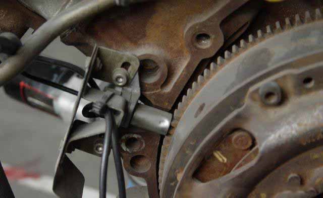
The sensor is installed on the flywheel plane at the rear of the engine or beside the pulley on the front end of the crankshaft.
2. Working principle
The crankshaft position sensor cooperates with the pulse disc to provide engine speed information and crankshaft top dead center information in a distributorless ignition system. The speed sensor consists of a permanent magnet and a coil outside the magnet. The pulse disc is a toothed disc, originally there are 60 teeth, but two teeth are vacant. The pulse disc is mounted on the crankshaft and rotates with the crankshaft. When the tooth tip passes by the end of the speed sensor, the pulse disc made of ferromagnetic material cuts the magnetic field lines of the permanent magnet in the speed sensor, and generates an induced voltage in the coil, which is output as a speed signal.
Three, failure phenomenon and judgment method
Fault phenomenon: unable to start, sudden flameout, etc.
General failure reasons: man-made failure, poor contact.
Maintenance precautions: During the maintenance process, use the press-in method instead of the hammering method to install.
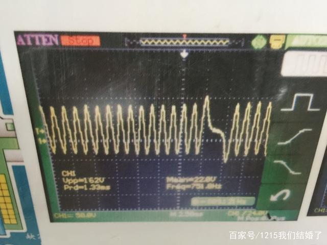

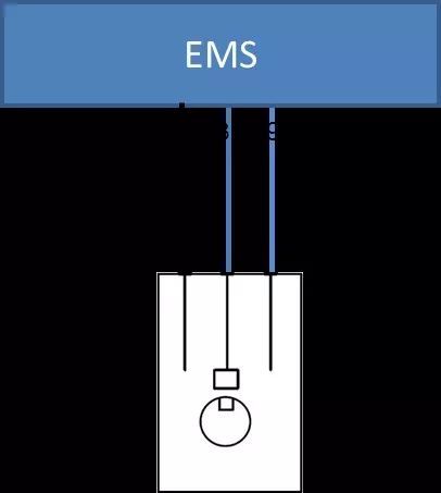
Simple measurement method: (remove the connector) turn the digital multimeter to the ohm range, connect the two test leads to the 2# and 3# pins of the sensor respectively, and the rated resistance at 20°C is 860Ω±10%. (Connect the connector) Switch the digital multimeter to the AC voltage range, connect the two test leads to the 2# and 3# pins of the sensor respectively, start the engine, and there should be a voltage output at this time. (It is recommended to check with a car oscilloscope, and you can view it. DG-6 passive type has a sine wave graph (as shown in the figure); DGU active type has a square wave graph.)


